
Single-Phase vs Three-Phase Transformers | A 3-Minute Guide
A transformer is a kind of equipment used in the electrical industry. It is used to change the voltage level of alternating current (AC) based on the principle of electromagnetic induction.
It is composed of three parts: primary winding, secondary winding, and a magnetic core. The three components work together to complete the coversion between electrical energy and magnetic energy. It achieves the voltage step up and step down, supplying appropriate electricity to different devices.
In real life, there are different power systems and load requirements. This requires that the transformers also be designed with different phases to match different requirements. A transformer with only one live (phase) wire and one neutral wire is called a single-phase transformer, while a transformer with three phase wires and possibly a neutral wire, is called a three-phase transformer.
Now let’s have a detailed discussion on the differences on single-phase vs three-phase transformers.

Why Understanding Single-Phase vs. Three-Phase Matters
Single phase transformers are commonly used in household and civil distribution voltage reduction these small scale scenarios, while three phase transformers are more suitable for large scale applications, such as industrial plants, transportation hubs, large buildings, solar energy, etc.
Understanding the difference between single phase and three phase power can help you make a wise choosen, avoid unnecessary spending and cost. You can:
✅ Ensure your electrical system matches the load requirements.
✅ Avoid unnecessary energy losses and high electricity costs.
✅ Make informed decisions on installation and future expansion.
✅ Ensure equipment compatibility and system stability.
Now let’s explain the single phase transformer firstly.
Single Phase Transformer Overview
What Is a Single Phase Transformer?
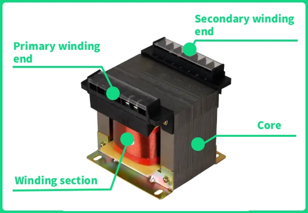
Single-phase transformer is composed of a single-phase iron core and two sets of windings, the primary and the secondary. Outside, it usually has two insulated bushings — one for live wire connecting and one for neutral wire connecting. Through the principle of electromagnetic induction, it converts high-voltage single-phase electricity into low-voltage single-phase electricity for direct use by residents.
Having understood the single phase transformer’s definition, let’s take a look at its key features.
▪️Its input and output are all single phase alternating current
▪️It usually has smaller rated capacity
▪️It is specially designed for low-power consumption
▪️Simple in design and compact in size, convenient installation
Principle of Operation of Single Phase Transformer
The single phase transformer works based on the law of electromagnetic induction – AC electricity generates a magnetic field in the primary coils, and the magnetic field will be transmitted to the secondary coils via the iron core to generate a different voltage electricity.

Single Phase Transformer Circuit Diagram

The above circuit diagram clearly shows how a single-phase transformer works. L₁ and L₂ are two key coils in the diagram, let’s analyze it from left to right.
🔘 On the left is the primary coil L₁. When an external AC voltage is applied. The current i₁ flows through this coil, generating an induced voltage e₁.
🔘 In the middle is the iron core. It plays as a bridge to transmit the magnetic field generated from L₁ to the secondary coil L₂.
🔘 On the right is the secondary coil L₂. It receives the changing magnetic field transmitted through the iron core and then induces an output voltage e₂. When a load is connected, the output current i₂ starts supplying power.
In simple terms, i₁ and e₁ are the interaction between electrical and magnetic at the input. And e₂ and i₂ are electrical energy that can be used directly at output. By adjusting the turn ratio between L₁ and L₂, the transformer can step up or down the voltage.
Types of Single Phase Transformers
Single phase isolation transformer: Its primary side is connected to the power grid, and the secondary side is connected to electrical equipment. Both sides are completely isolated, thus the harmonics can be isolated and weaken and the fault transmission is prevented.
Single phase auto transformer: It only has one set of windings and no electrical isolation function. The windings can be set with different connection points to slightly adjust the output voltage. For example, adjusting the 220V civilian voltage to 200/240V to adapt to small devices.
Dry-type single-phase transformer: Its windings and core are wrapped with epoxy resin and dissipate heat by air. There is no liquid in a dry type transformer. It is safe, moistureproof and maintenance-free.
Oil-immersed single-phase transformer: Its windings and core are immersed in insulating oil, and the heat generated is dissipated by the insulating oil. The oil immersed type is very suitable for outdoor utility poles in rural areas and suburban areas. It is also called single phase pole mounted transformer.
Single phase core type transformer: The core is the main frame, and the windings are wound around the core column. There are EI-type, C-type, R-type, wound core types.
Applications of Single Phase Transformers
Single-phase transformers are commonly used in household appliances and industrial equipment in the power system.
Residential electricity supply: The most common daily application. The pole-mounted transformers or small community substations reduce the higher voltage down to standard household voltage.
Local lighting and small commercial power: Provides single-phase low-voltage power for shops, small offices, streetlights, etc.
Electronic device adapters: Tiny single phase transformers can be installed to phone chargers, laptop power supplies, and appliance controllers to convert voltage to the lower voltages required by the device (5V or 12V).
Safety isolation: The single phase isolation transformer is used in workshops, labs, or damp environments. Reduce the risk of electric shock and ensure personal safety.
Equipment control and triggering: Provides specific voltages for certain industrial equipment, such as welding transformer single phase.
Impedance matching: In older audio devices or some communication circuits, used to match the impedance between circuits for maximum signal power transfer.
Three Phase Transformer Overview

What Is a Three Phase Transformer?
A three phase transformer is used to change the voltage level (step up or down) of a three phase alternating current (AC). It works on the same principle of the single phase transformer – generate electricity by magnetism.
A 3 phase transformer has one single iron core and three sets of windings (corresponding to Phase A, Phase B, and Phase C). Its primary (input) and secondary (output) sides all include three sets of coils. The windings can be connected in either a star (Y) or delta (Δ) configuration based on the voltage transformation requirements.
It is the mainstay in industrial and high-power electrical systems, and it makes a great contribution in transmitting and distributing large amounts of electrical energy. Its main features:
✅ Save more space: Compared with using three single-phase transformers together, a three-phase transformer is smaller in size and more compact in structure.
✅ More stable and stronger: It can help maintain the stable output of three-phase electrical balance. It is particularly suitable for driving large industrial equipment, such as machine tools and large motors.
✅ More economical: It is capable of handling much higher power loads than 1 phase transformers. So it is more economical for heavy-duty and large-scale applications.
Working Principle of 3 Phase Transformer
You can imagine a three-phase transformer as three single-phase transformers sharing one iron core. In our daily single-phase electricity, electrical energy is delivered in pulses one after another. While in three-phase electricity, there are three alternating currents (Phase A, Phase B, Phase C). They are not delivered one after another, but at off-peak time – after one reaches its peak, the next catches up. Three phases electric relay run, thus forming a stable and powerful electrical energy.
A three-phase transformer can also be connected to only the high and low voltage windings of one phase. In this case, it can be used as a single-phase transformer. However, we do not recommend doing so, because in this condition, the cores of the other two phases are in a no-load state. Compared with the full load state of three phase, this practice (three phase to single phase) is less efficient.
3 Phase Transformer Diagram

This picture clearly shows the internal structure of a three-phase transformer used in a 10kV distribution system. The key components are the primary winding on the high-voltage side and the secondary winding on the low-voltage side.
The rated voltage on the high-voltage side is 10kV. It is usually connected with the power grid. The low-voltage side outputs a lower voltage (for example, 400V/230V) for the use of end users.
Please pay attention to the “No neutral line” marked in the figure. It means the high voltage side adopts a three-phase three-wire system (usually with a delta/Δ connection) and no neutral wire exists. In contrast, the low-voltage side is usually with a star (Y) connection, where a neutral line can be drawn out. This creates a three-phase four-wire output. This design can provide phase voltage (for example, 230V) and line voltage (for example, 400V) in the meantime to meet the different power demands of single-phase and three-phase loads.
Three Phase Transformer Working Process and Electrical Isolation
Here’s how the transformer work and achieve electrical isolation.
The Structure: One Core, Three Pairs of Coils
There’s one single iron core with three core limbs inside the shell.
Around each limb, two coils are wrapped: One is the primary coil (input side), and the other group is the secondary coil (output side). So, there are three primary coils (A, B, C) and three secondary coils (a, b, c).
The Working Process (Step-by-Step)
Step 1️⃣: Three separate AC voltages (120 degrees apart) enter the three groups of primary coils (A, B, C) respectively.
Step 2️⃣: The three alternating currents in the primary coil jointly form a powerful rotating magnetic field within the iron core. This magnetic field is very strong and constant.
Step 3️⃣: This rotating magnetic field cuts across all three secondary coils (a, b, c) at the same time.
Step 4️⃣: According to Faraday’s law, a voltage is induced in each secondary coil. Due to the smooth rotation of the magnetic field, we can obtain three perfectly synchronized AC output voltages from the secondary side.
The Magic of Connections (Star & Delta)
This is the clever part! We can use two main ways to connect the ends of the coils to get different voltages.
🔘 Delta (Δ) Connection: Connects the coils in a triangle. It is robust, provides higher current, and is perfect for heavy-duty industrial motors and machinery.
🔘 Star (Y) Connection: Connects one end of all three coils together. It provides a neutral wire and is good for lower current and providing both high voltage (for industry) and lower voltage (for lighting/offices) simultaneously.
Types of Three Phase Transformers
Three-phase transformers are core equipment in power systems. According to different classification standards, the main types are as follows:
Power transformers: Used for stepping up or stepping down voltage in transmission and distribution systems, with a wide capacity range (e.g., 11kV/400V distribution transformers).
Distribution transformers: Supply power directly to end-users, commonly found in industrial zones, commercial buildings, and residential areas.
Special transformers:
Rectifier transformers: Provide power for DC equipment such as electrolysis and electroplating.
Furnace transformers: Deliver high-current, low-voltage power for arc furnaces and induction furnaces.
Traction transformers: Used for electrified railway power supply.
Three phase three winding transformer: Each phase’s core is wound with three sets of coils, one for input voltage and two for output voltage. This transformer can supply power to two different voltage devices at the same time.
Three-phase bank transformers: Composed of three independent single-phase transformers, offering flexible transportation but at a higher cost.
3 phase core type transformers: Feature a three-legged core with a shared magnetic circuit, offering compact structure, low cost, and the widest application.
Off-circuit tap-changing transformers: Manual tap adjustment after power-off, used in scenarios with minimal voltage variation.
On-load tap-changing transformers: Automatic tap adjustment while energized, maintaining stable output voltage for critical loads.
Applications of Three Phase Transformers
Three-phase transformers are essential equipment for stepping up, stepping down, and isolating three-phase AC power. They are widely used in various high-power scenarios due to their stability, efficiency, and strong transmission capacity. Their main application areas include:
Industrial Power Distribution
Used in factories, workshops, and production lines to power large motors, compressors, welding machines, and other industrial equipment.
Commercial & Building Power Supply
Provide stable three-phase power for large buildings such as malls, data centers, and hospitals, supporting air conditioners, elevators, and backup power systems.
Power Grid Transmission & Distribution
Key equipment in substations for stepping up voltage at power plants or stepping down voltage for city distribution networks.
Renewable Energy Systems
Used in solar and wind farms to step up voltage for grid connection, improving power transmission efficiency.
EV Charging Stations
Support high-power fast-charging piles, especially suitable for highway service areas and commercial vehicle charging centers.
HVAC & Cooling Systems
Ensure stable operation of central air conditioning units, chillers, and cooling towers in large buildings.
Mining & Heavy Industries
Meet the high demands of mining machinery, drilling equipment, and other heavy-load applications for robust and reliable power supply.
How to Choose Between Single-Phase and Three-Phase Transformers
Consider the following four factors to choose between a single-phase transformer and a three-phase transformer to satisfy your own needs.
Load Size
If your usage is for light loads, such as household appliances or low-power devices, use a 1 phase transformer. Since the 1 phase transformer is designed specially for small loads and 220V/230V/240V single-circuit power supply.
However, if for large motors, industrial equipment or even large commercial buildings, choose a three phase transformer. Because these applications need higher power capacity and more stable operation, and only a three phase transformer can provide.
For a special situation, if the continuous loads is above 10 kW, OMEK expert recommend use a three-phase system.
Your Installation Environment
Single phase transformers usually serve homes, rural areas and small shops. While the three phase transformer usually serve factories, data centers, large commercial complexes. The three phase transformer can meet the demands of high-impact, high-current equipment.
🔹OMEK kindly reminder: If your space is limited, consider compact three phase transformers (such as an epoxy cast resin dry type transformers).
Future Power Expansion Plans
If you have small locations and your electricity demand is fixed and have no plan to increase the power equipment or expand capacity. A single-phase is sufficient. You will have the lowest cost and simplest maintenance.
If your project is with room for future growth, we recommend that choose a three-phase transformer directly. Because three-phase systems are easier to expand than single-phase systems and do not require subsequent rewiring.
Single Phase and Three Phase Transformer Manufacturer

OMEK Power is an enterprise professional in power transformers and distribution transformers manufacturing. It integrates R&D, production, sales, and technical services. Our main products include single-phase and three-phase distribution transformers, high and low voltage switchgear, outdoor compact substations and step voltage regulators. Besides, we also provide efficient solutions for global customers.
From raw material procurement to final product inspection, each process meets international standards and customer requirements. In 2025, OMEK exports over 15,000 single-phase oil type transformers, 40,000 three-phase oil immersed transformers and over 1,200 three-phase dry type transformers. Our products have earned long term trust from overseas clients.
If you have any questions regarding the selection of single-phase or three-phase transformers, OMEK Power’s professional technical team can provide you with customized solutions. Click here to send us emails, and we will reply to you within 24 hours due to the time zone difference.

Posted by Victoria leave words
Thanks for reading! Hope you enjoy this article. If you have any questions about this blog, please leave a comment below, or contact OMEK's online customer service. Looking forward to having in-depth communication with you!
Leave a Reply