
Transformer Laminated Cores: A Complete Guide to Materials, Types, and Efficiency
Every transformer core faces the same challenge: convert electrical energy into magnetic flux without producing heat. The solution? Laminated cores. By stacking thousands of thin, insulated silicon steel sheets instead of using a solid block of iron, engineers reduce eddy current losses by over 95%, extend equipment lifespan by decades, and control noise levels. Here’s everything you need to know about lamination mechanics, materials, and the trade-offs between core types.
A Brief Introduction to Laminated Cores
What are laminated cores?
The magnetic transformer core consists of hundreds of individual ultra-thin electrical steel sheets stacked together instead of a single block of metal. Each individual is usually 0.23 mm to 0.35 mm thick, and is paper-thin in terms of electrical insulation.
This multi-layer structure will simultaneously help to fulfill two functions:
· Give a High-Permeability Path: The steel lets the magnetic flux to go easily through the core.
· Block Electrical Conductivity: The insulating layers physically block currents from flowing in loops, making the unwanted flow of electrical currents between sheets very difficult.
Solid Cores vs Laminated Cores: What’s the difference?

| Solid Cores vs Laminated Cores | ||
| Parameters | Solid Cores | Laminated Cores |
| Construction | One-piece cast or forged steel | Thousands of thin stacking silicon-steel sheets |
| Insulation Between Layers | None | Each sheet coated with an insulating oxide layer or varnish |
| Eddy Current Loss | Extremely high ( over 20–30% of total losses in AC applications) | Minimal (typically < 1% of total losses) |
| Heat Generation | Severe internal heating | Low temperature rise |
| Mechanical Stability | Prone to cracking under extreme heat and cold | Resilient as laminations can expand independently |
| Cost | Lower initial cost | Higher manufacturing cost |
| Applications | DC electromagnets, magnetic yokes for particle accelerators, very low-frequency (< 10 Hz) devices | All AC power transformers, motors, generators, and inductors (50 Hz –400 Hz) |
| Core Loss at 50Hz (Typical) | ~ 10–15 W/kg (unsuitable for continuous AC operation) | ~ 0.8–1.2 W/kg for standard M4 grade; ~ 0.5–0.7 W/kg for high-grade amorphous/nanocrystalline |
The Science Behind It: How Laminated Cores Reduces Eddy Currents
What Are Eddy Currents in Transformers?

A current which circulates in a metallic conductor due to a changing magnetic field is called an eddy current, or Foucault’s current.
The magnetic flux in an AC transformer is continually changing. Faraday’s Law of Electromagnetic Induction says that this change in flux creates a voltage in the secondary winding, and within the core as well. Iron and steel are conductive materials and these electric potentials generate closed loops of currents swirling around within the iron or steel solids, just like whirlpools in water.
| Pro Insight: Engineers usually only focus on core lamination. In practice, however, 3D FEA simulations, such as 17 MVA / 35 kV class transformers, show that leakage magnetic fields can penetrate the core, generating high secondary eddy currents in structural steel, such as oil tank walls and clamping frames. Local flux densities as high as 0.083 T can be developed by unshielded structural eddy currents, which lead to high hot spots that cause deterioration of the transformer’s oil.
The Mechanism: How Thin Sheets & Insulation Break Current Loops
Transformer designers don’t change the magnetic characteristics of the steel, but instead they physically break the electrical path of the steel to prevent the eddy currents.
· The Layered Architecture: The core is made of thousands of super thin steel sheets, stacked side by side and parallel to the magnetic flux.
· Insulation Barrier: A very thin layer or coating, of a very high electrical resistance, is applied in each case to provide electrical insulating function, such as varnish or inorganic oxide coating.
· How It Works: Magnetic flux will freely pass from one sheet to the next, but the electrical resistance of the coating on the sheets will prevent the current from “jumping side to side”.
The Core Logic: The concept is to distribute a single large amplitude eddy current loop into thousands, each being isolated, by lamination. The losses of eddy current are proportional to the square of width of the path of the current, and the total eddy loss is very small due to these small loops.
How Laminated Cores Thickness Affects Core Efficiency
The classical eddy current loss formula Pe = k × f 2 × B2m × t 2, shows that the power loss is directly proportional to the square of the lamination thickness (t). This mathematical relationship basically proves that the thickness control is very important in modern transformer production: for example, whether to use 0.23 mm, 0.27 mm or 0.35 mm sheet.
| Thickness | Typical Core Loss (50 Hz, 1.7 T) | Relative Eddy Loss | Relative Material Cost | Stacking Labor | Applications |
| 0.23 mm | 0.85–1.05 W/kg | 1.0 × (baseline) | 1.25–1.35 × | ~1.5 × | Premium efficiency / HVDC / EV |
| 0.27 mm | 1.00–1.20 W/kg | ~ 1.4 × | 1.0 × (baseline) | ~1.2 × | Most 50Hz power transformers |
| 0.35 mm | 1.20–1.44 W/kg | ~ 2.3 × | 0.85–0.90 × | 1.0 × (baseline) | Cost-sensitive projects / Legacy specs |
Why Silicon Steel Is Used in Laminated Cores?
What Are Silicon Steel Laminations?
Silicon steel, or electrical steel is a type of iron-silicon alloy that has been specially developed to have very high magnetic and electrical resistance.
Metallurgists add a specific quantity of silicon (which is typically 2%–4.5%) into the iron to get a material with a particular property of electromagnetic induction. Silicon steel laminations are typically used for the industry standard cores of transformers, the stators of electric motors and the inductors.
| Pro Insight: In addition to core loss, which is the most talked about noise source, magnetostriction, or “breathing” of steel in a magnetic field is the source of low frequency noise and structural vibration in transformers. Over-tight clamping or poor core assembly can cause compressive stress, which can increase the magnetostriction by almost 4 times, resulting in a quiet transformer becoming a noisy transformer.
The Role of Silicon in Laminated Cores
· Increases Electrical Resistivity: Pure iron conducts electricity too well, which is bad here as it allows eddy currents to flow freely and dissipate energy. The electrical resistance increases four to five times when silicon is added. The eddy currents can’t flow as strongly when there is more resistance. What is the best thing about it? It does this while not decreasing the magnetic flux carrying capacity of the steel.
· Reduces Hysteresis Loss: The small magnetic domains in the core have to change direction with every change in the direction of the AC voltage, which changes 50 or 60 times a second. The energy is lost as heat due to internal friction resulting from that flipping. These domains can be flopped with less force when silicon is added, and the hysteresis loop is made smaller, making the iron “softer” magnetically.
Key Manufacturing Process: From Raw Alloy to Finished Core
Cold Rolling: Cold rolling means being rolled into accurate thickness, such as 0.23mm-0.35mm under the effect of cold, the process causes the steel to be mechanically stressed and the crystalline grains are aligned.
Annealing: Thinning into thin laminations by stamping and shearing creates a great deal of mechanical stress that will destroy the alignment of the magnetic domains. The purpose of the high temperature stress-relief annealing is to restore the core’s magnetic permeability and reduce core losses.
Insulation Coating (Color & Classification): After the rolling and annealing stages, the sheet is coated on both sides with a microscopic inorganic or organic coating (C-3, C-5, phosphate coating etc.).
What the Color Tells You: The Commercial silicon steel laminations have different surface colors, depending on the type of coating and the method of processing:
| Surface Color | Coating Type | What It Indicates |
| Silvery-grey matte | As-rolled or annealed surface with a low level of oxide layer | Basic surface as found in older grades or surfaces not coated |
| Bluish-grey / Dark grey | Thermal oxide layer formed during high-temperature annealing | Indicates that the CRGO has been exposed to high temperature annealing atmosphere, common for fully processed CRGO |
| Golden-brown / Straw | Chromate-free inorganic coating (e.g., phosphate-based or C-5 type) | Modern environmentally-friendly coating; provides excellent insulation and good punchability |
| Light green / Greenish-grey | Organic or semi-organic insulation coating (C-3 type) | Usually used where higher surface insulation resistance is needed; more widely used in motor |
| Iridescent / Rainbow hues | Thin oxide interference film or specialized coating | Thin-film interference effect; commonly found in high quality laser scribed CRGO coated with special film |
| Real Cases in Point: In our shop, we would construct an S11-50000/110 core which is composed of 14,500 sheets of steel stacked 2,900 layers high; each layer is 28 tons of steel. It took 6 of our guys 16 hours to stack everything manually.
Types of Laminated Cores
Classified by Shape:
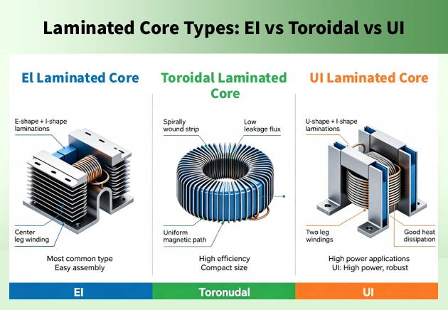
| Features | EI Laminated Core | Toroidal Laminated Core | UI Laminated Core |
| Shape | Rectangular, stacked E + I laminations | Ring, wound from one-piece strip | Rectangular, stacked U + I laminations |
| Magnetic Circuit | Open | Fully closed | Open |
| Leakage Flux | High | Very low | High |
| Efficiency | Moderate | Highest | Moderate |
| Winding Difficulty | Easy | Difficult | Easy |
| Manufacturing Cost | Low | High | Medium-high |
| DC Bias Sensitivity | Low | High | Low |
| Typical Power Range | < 5 kVA | 10 VA – several kVA | > 5 kVA |
| Typical Applications | Small power transformers, audio output transformers, general isolation transformers | High-end audio, precision instruments, medical equipment | High-current reactors, multi-winding custom designs, industrial power supplies |
Classified by Material:
| Materials | Key Characteristics | Typical Applications |
| CRGO | The industry standard for power transformers, highest permeability along rolling direction, lowest core losses (0.85 – 1.20 W/kg @ 50Hz, 1.7T) and large inductors. | Power transformer cores, high-efficiency distribution transformers, large inductors |
| CRNGO | Non-Isotropic properties (different performance in different directions); higher permeability; lower losses (3.5 – 2 W/kg @ 50Hz, 1.7T) (rarely used in transformers, but used in small inductors and rotating machines) | Motor stators and rotors, small inductors, rotating machinery (rarely used in transformers) |
| Amorphous Core | Extremely low core loss (0.15 – 0.30 W/kg @ 50Hz, 1.3 – 1.4T — just 1/5 to 1/3 of CRGO; much thinner strip (~ 0.025mm); low saturation flux density (~ 1.56T); brittle and difficult to process | High-efficiency distribution transformers (no-load-loss-dominated applications, e.g., rural grids), high-frequency inductors |
| Nanocrystalline Core | Ultra-low core losses (0.14 – 0.21 W/kg @ 50Hz, 1.4T); extremely high permeability; excellent high-frequency performance; expensive; low saturation flux density (~ 1.2T) | High-frequency transformers, common-mode chokes, EMI filters, EV onboard chargers — dominant above kHz range |
How Laminated Cores Improves Efficiency & Lifespan
· Reduce Energy Loss
Thinner laminations cut eddy current losses by 25–30%, saving 8,000–10,000 kWh/year (up to $ 30,000 over 30 years for a large core). The first year or more of high-grade steel premiums is offset by the savings within 3-4 years.
· Reduce Temperature Rise
The smaller the eddy current loops, the less internal core heat suppression. Each 8-10°C drop in temperature doubles the life of the insulation, so for every degree cooler the cores will be, the thermal degradation is slowed and the lifespan is extended for decades.
· Reduce Magnetostriction & Acoustic Noise
A new advanced step-lap lamination technique that controls clamping stress, reduces magnetostriction up to 90%. This cuts down on the overall noise level 2-5 dB and ensures complete noise compliance for installations where noise is a concern such as hospitals and residential areas.
Conclusion
Laminations eliminate the energy loss due to eddy currents. Magnetic path passes through the grain-oriented steel and is not blocked by the insulation and thin sheets which make up the loops. When successful, the core will not only operate quieter, but will consume less energy and provide longevity of decades.
Searching for high-efficiency, ultra-low noise transformer solutions? At OMEK, we design and produce custom laminated cores and complete distribution transformers to international grid standards. Contact us now!

Posted by Victoria leave words
Thanks for reading! Hope you enjoy this article. If you have any questions about this blog, please leave a comment below, or contact OMEK's online customer service. Looking forward to having in-depth communication with you!
Leave a Reply