


10 kVA Pole Mounted Transformer | Single Phase Distribution Transformer
OMEK 10 kVA pole mounted transformer is a single phase oil immersed distribution transformer, designed for rural electrification, telecom base stations and isolated micro-load applications. It meets ANSI/IEEE C57.12.20 and IEC standards.
- Rated Capacity: 10 kVA
- Primary Voltage: Up to 34.5 kV
- Secondary Voltage: 120/240V, 220/230V
- Protection Types: Conventional & CSP Available
- Anti-Corrosion Level: Up to C5-M Heavy-Duty Protection

Key Features of 10 kVA Pole Mounted Transformer
Weighing 80-130 kg, an ultra-lightweight 10 kVA overhead transformer only requires single-pole mounting without a heavy crane or concrete foundation.
Primary voltage up to 34.5 kV and customizable secondary voltage configurations, including 120/240V.
A 10 kVA pole mounted transformer perfectly powers low-power isolated loads, significantly reducing no-load losses in the daily life.
Seam welding and NBR gaskets provide a fully sealed tank that prevents moisture and air leakage, ensuring there is no leakage of oil over the 30+ year service life.

OMEK 10 kVA Single Phase Overhead Transformer
Capacity 10 kVA Customizable | Primary Voltage 2400 V to 34500 V Customizable |
Secondary Voltage 110 V to 690 V Customizable | Tapping Range ±2 x 2.5% Customizable |
Impedance Voltage 1.5% – 3.0% Customizable | Rated Frequency 50 Hz, 60 Hz Customizable |
Fluid Type Mineral Oil, Vegetable Oil Customizable | Cooling Type ONAN |
Core Material Silicon Steel, Amorphous Alloy Customizable | |
| Technical Specs | D13-M Series (Ultra-Low Loss Core) | D11-M Series (Standard Efficiency) |
|---|---|---|
| Phase | Single phase | Single phase |
| High Voltage (kV) | 6 / 6.3 / 10 / 10.5 / 11 | 6 / 6.3 / 10 / 10.5 / 11 |
| Low Voltage (kV) | 2 × (0.22~0.24) or 0.22~0.24 | 2 × (0.22~0.24) or 0.22~0.24 |
| Frequency (Hz) | 50, 60 | 50, 60 |
| Tapping Range | ± 2×2.5% | ± 2×2.5% |
| Total Weight (kg) | 80-130 | 80-130 |
| Connected Group Lable | Ii0, Ii6 | Ii0, Ii6 |
| No-Load Loss (W) | 36 | 45 |
| Load Loss (W) | 235 | 235 |
| No-Load Current (%) | 1.1 | 1.1 |
| Short Circuit Impedance (%) | 3.0 | 3.0 |
| Insulation Class | Class A | Class A |
| Temperature Rise | 65 ℃ | 65 ℃ |
| Enclosure Protection Rating | IP54, IP65 | IP54, IP65 |
| Overall Dimension (L×W×H, inches) | 18.3 × 19.7 × 39.8 | 18.3 × 19.7 × 39.8 |
| Mounting Dimension (L×W, inches) | 7.9 × 17.7 | 7.9 × 17.7 |
Why Choose 10 kVA Pole Mounted Transformer
Ultra-Low Loss Core
OMEK 10 kVA single phase pole mounted transformers are equipped with high-permeability CRGO silicon steel core laminations.
This design significantly reduces no-load losses, exceeding ANSI/IEEE C57.12.20 and DOE 2016 energy efficiency standards.


High-Purity Electrolytic Copper Windings
OMEK utilizes 100% pure copper or high-grade aluminum windings (customizable) insulated with thermally upgraded kraft paper.
That ensures superior performance in short-circuit strength, thermal dissipation, and overload capacity.
Heavy-Duty C5-M Anti-Corrosion Tank
OMEK 10 kVA pole mounted transformers utilize high-grade steel with rigorous shot blasting and powder coating, and pass 2,000+ hours salt spray test.
You can choose whether 304 or 316L stainless steel suits your coastal, marine, or tropical application.

Flexible Protection System Options
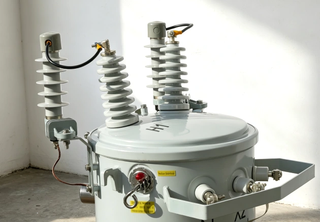
OMEK offers two configurations. The conventional type offers a low-cost solution with external cutout fuses and surge arresters.
The CSP type comes with pre-installed internal circuit breakers, overload indicators, and tank-mounted arresters, cutting installation labor by up to 40%.
Accessories


Application


Related Products


Need 2D/3D CAD Drawings for Your Project?
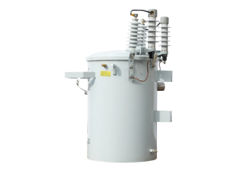
Contact OMEK to get a 10 kVA Pole Mounted Transformer dimension sheets, pole mounting bracket layouts, and technical schematics. Available in PDF, DWG, DXF, and STEP formats.
Pre-Shipment: What OMEK Does for Your Order

All transformer tanks are filled with nitrogen to test high-sensitivity seam seals, ensuring there is no leakage of oil over the 30+ year service life.

Checks voltage transformation ratios and winding polarity of transformers against the design parameters, ensuring stable power delivery under full load conditions.

Measures excitation losses and copper/aluminum winding resistance, ensuring energy efficiency meets the ANSI/IEEE DOE standards.
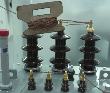
High-voltage applied and induced AC withstand tests are performed on HV/LV bushings to demonstrate the withstand capability of bushing under lightning or grid surge.

To avoid premature internal arc discharge, 100% in-house oil sampling tests the moisture content and dielectric breakdown voltage (>40 kV).

Your transforners are wrapped with vacuum moisture barriers and packed in heavy-duty wooden crates. Official Factory Acceptance Test reports are attached.
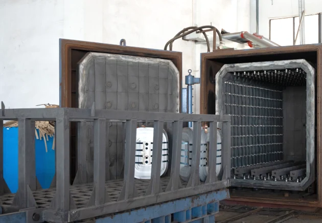
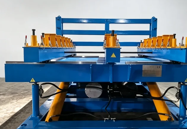
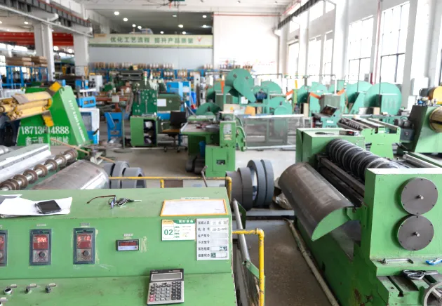
OMEK Smart Factory & Quality Testing




FAQs
Have any questions? We’re here to help you out.
Formula: 10,000 VA / 240 V=41.67 Amps. Theoretically, it can deliver about 41.67 amps, which, however, is under full-load conditions. For a load that will run for more than 3 hours, it’s recommended to select a transformer larger than the actual load to avoid overheating.
Total Weight (kg): 80-130
Overall Dimension (L×W×H, inches): 18.3 × 19.7 × 39.8
Mounting Dimension (L×W, inches): 7.9 × 17.7
| Parameter | D11 | D13 |
| Transformer Loss | Standard | Lower |
| Initial Cost | Lower | Higher |
| Operating Cost | Higher | Lower |
| Best For | Cost-focused projects | Long-term energy efficiency |
When you choose the right transformer, remember to take into consideration: project specification, loading conditions, operating hours, applications, and lifecycle cost.
For other capacity options, you can also explore our 25 kVA pole mounted transformer, 37.5 kVA pole mounted transformer, 50 kVA pole mounted transformer, 100 kVA pole mounted transformer & 150 kVA pole mounted transformer.
Step 1: Use through-bolts to attach the heavy-duty mounting bracket to the utility pole.
Step 2: Hook up the unit (~100kg) with the bucket truck winch or gin pole and attach it to the bracket.
Step 3: Tie the tank ground terminal to the lightning and fault protection pole down-ground rod.
Step 4: Install secondary LV lines (120/240V). For the conventional type, install a cutout fuse/arrester; for the CSP type, connect primary HV lines directly.
Step 5: Verify electrical clearances, energize line and measure output voltage prior to connection of load.
OMEK provides flexible payment terms depending on your order quantity, including T/T, D/P, L/C at Sight, etc.
Yes. OMEK offers full customization on kVA rating, high/low primary voltages, tapping range, vector groups, rated frequency, dual-voltage outputs, short-circuit impedance, enclosure material, winding material, core material, packing method.