
Transformer Routine Tests: Types, Procedures & IEC Standards
Pre-delivery routine tests of transformers are performed to verify electrical performance, test insulation integrity, and look for potential manufacturing defects.
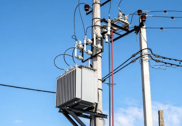
These tests are carried out to ensure that every transformer conforms to specified technical requirements in accordance with the applicable IEC 60076 standards. This guide covers routine test types, procedures, purposes, acceptance criteria, and potential risks of test failures.
What Are Routine Tests?
Transformer routine tests are performed on each units before delivery to ensure that it satisfies the relevant standards and specific technical requirements.
Depending on the transformer type and design, tests are conducted in compliance with the IEC 60076 standards: IEC 60076-1, IEC 60076-3 and IEC 60076-11. There are procedures and acceptance criteria for each test.
Why Routine Tests Matter?
✅️ Check Electrical Performance: Determine the difference between specified and observed values of important parameters that may impact transformer performance including voltage ratio, power losses, etc.
✅️ Detect Manufacturing Defects: Identify potential issues with windings, electrical connections, and insulation before delivery.
✅️ Reduce Operational Risks: Minimize the risk of failures, unexpected downtime, and costly repairs after installation.
✅️ Support Customer Acceptance and Traceability: Give test records that enable customers to confirm the quality of the product and the results of the tests during quality checks or troubleshooting.
Routine testing minimizes the chance of the delivering non-conforming transformers. Passing routine tests does not, however, ensure that a transformer will never fail during its operation; Other factors such as correct installation and maintenance and operating conditions are also important.
Routine Tests vs Type Tests vs Special Tests
| Routine Tests vs Type Tests vs Special Tests | |||
| Routine Tests | Type Tests | Special Tests | |
| Main Purpose | Detect manufacturing defects and verify key electrical parameters of each transformer | Verify design performance, such as temperature rise, insulation withstand, and short-circuit withstand capability | Evaluate additional characteristics or specific performance requirements not included in routine tests |
| When performed | Before delivery on each and every unit | Upon introduction of a new design; sampling tests every five years | Based on specific customer requirements |
| Typical examples | Winding resistance, voltage ratio, load loss, and dielectric tests | Temperature-rise test, lightning impulse test, and sound-level measurement, depending on the applicable standard | Capacitance measurement, special dielectric tests, and other agreed tests, depending on the applicable standard |
| Required for every unit? | Yes | No | No |
Transformer Routine Tests According to IEC Standards
The routine tests of transformer are carried out based on IEC 60076 standards. Specific requirements vary according to the type, design and rated specification of the transformer.
- IEC 60076-1 C General Requirements: Provides general requirements for power transformers and some of the routine tests, such as winding resistance, voltage ratio, load loss, no-load loss measurements.
- IEC 60076-3 C Insulation Levels and Dielectric Tests: Covers insulation levels and various dielectric tests such as applied-voltage or induced-voltage tests.
- IEC 60076-11 C Dry-Type Transformers: Specifies requirements for dry-type transformers, including their applicable routine tests, such as partial discharge measurement.
Differences Between Oil-Immersed and Dry-Type Transformer Routine Tests
Common Tests for Both Types:
Winding resistance measurement
Voltage ratio and phase displacement test
Short-circuit impedance and load loss measurement
No-load loss and no-load current measurement
Applied-voltage test
Induced-voltage withstand test
Specific Tests for Oil-Immersed Transformers:
✅️ Tank leak or tightness tests: Determine if the tank and sealing system will prevent the insulating liquid from leaking.
✅️ Insulating liquid tests: Test the appropriate properties of the insulating liquid, as required.
✅️ Core and frame insulation checks: For designs with insulated cores or frames as needed.
Specific Tests for Dry-Type Transformers:
✅️ Partial discharge measurement: A routine test specified by IEC 60076-11.
✅️ Insulation system checks: Ensure the performance of the solid insulation system by performing the appropriate dielectric tests.
Other tests, such as on-load tap-changer operation and built-in current transformer ratio and polarity checks, are carried out if applicable to the required transformer design.
Types of Transformer Routine Tests
Winding Resistance Measurement
This test checks the condition of winding joints, lead connections, and tap-changer contacts, and reveals abnormal resistance which can be a sign of poor connections or a defect in the winding.
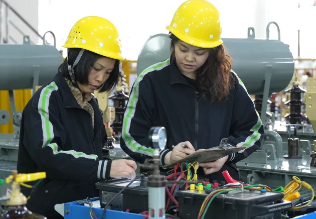
Testing Equipment: Transformer Winding Resistance Meter
HV Side: Check line resistance unbalance and measure the winding resistance at each tap position.
LV Side: LV side has the neutral terminal, so both line resistance unbalance and phase resistance unbalance should be checked.
OMEK Standards: In both HV & LV sides, the line resistance unbalance 2%, while phase resistance unbalance 4%. OMEK‘s measured line resistance unbalance is typically around 0.0*%, far below the standards.
Risks of Failure: Failure of this test may cause localized overheating, more power losses, further deterioration of electrical connections, and transformer failure during operation.
Voltage Ratio and Phase Displacement Test
This test checks the winding turns ratio, confirms the correct vector group and phase displacement, and checks voltage ratio errors at different tap positions.
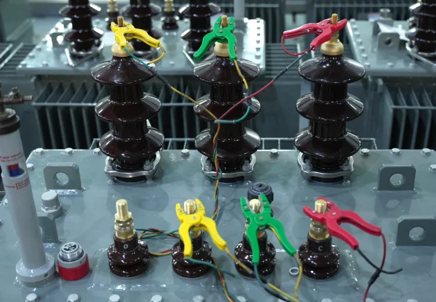
Testing Equipment: Transformer Turns Ratio Tester
Basic Procedure: Connect a transformer turns ratio tester to the high-voltage and low-voltage windings. Measure the voltage ratio at each tap position and verify the vector group and phase displacement.
OMEK Standards: OMEK measures the voltage ratio error at each point of the taps. The error is to be less than 0.4% at the principal tap position and not to exceed 0.5% at any other tap position. The acceptance criterion for the internal inspection is 0.4%.
Risks of Failure: Test failure may cause the output voltage to be too high or too low and unstable voltage regulation. High circulating currents could occur if the transformers are operated in parallel with an incorrect connection of the vector groups, which could damage the equipment.
Short-Circuit Impedance and Load Loss Measurement
This testing is done to measure short-circuit impedance and winding load losses.
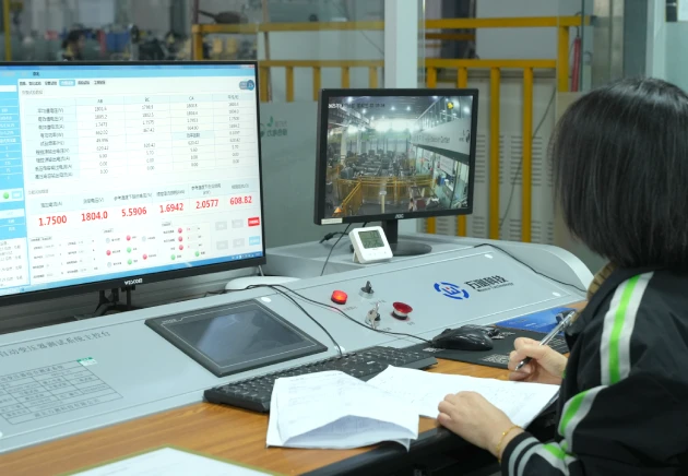
Testing Equipment: Transformer Loss Measurement System, Test Power Supply and Short-Circuit Test Setup
Basic Procedure: Short circuit one winding and apply a lowered voltage on the other winding until the specified test current is reached, measuring load loss and short circuit impedances. Compare the results with the customer’s technical requirements.
OMEK Standards: Test results are evaluated based on customers’ technical agreements or project specifications.
Risks of Failure: Any serious loss of load may lead to overheating of the transformer and decrease energy efficiency. Excessive voltage drop under load or alteration of short circuit currents may be caused by abnormal short-circuit impedance.
No-Load Loss and No-Load Current Measurement
To measure core losses and no-load current under rated voltage and frequency.
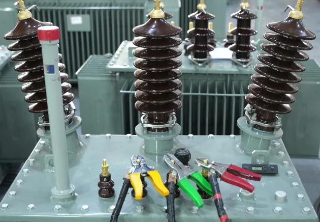
Testing Equipment: Transformer Loss Measurement System, Precision Power Analyzer
Basic Procedure: Apply rated voltage at the rated frequency to one winding with the other winding open. Measure and record the no-load loss and no-load current.
OMEK Standards: No-load loss must meet customers’ technical agreements or project specifications. No-load current should also be measured and recorded for verification.
Risks of Failure: Excessive no-load loss will increase the consumption of energy during the entire service life of the transformer. High no-load current can signal some defects in the core or insulation, which could impact transformer performance and reliability.
Applied Voltage Test
To confirm the insulation ability between the high voltage winding, the low voltage winding and the ground under the power frequency test voltage.
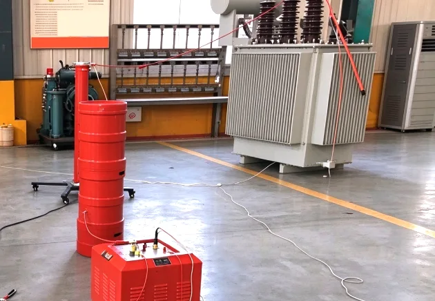
Testing Equipment: AC Withstand Voltage Tester
Basic Procedure: Connect the voltage being tested to the high-voltage winding, connecting the low-voltage winding to ground. Then retest the low voltage winding using the same test procedure. Hold the test voltage for 60 seconds and observe whether there is voltage collapse, insulation breakdown or flashover.
OMEK Standards: The test voltage is maintained for 60 seconds. If there is no insulation breakdown or flashover and the test voltage is stable during the test, the transformer passes the test.
Risks of Failure: During operation, insulation failure can cause leakage current, short circuit or electrical breakdown, which can cause transformer damage or unexpected downtimes.
Induced Voltage Withstand Test
This test verifies the insulation between turns and layers of transformer windings.

Testing Equipment: Induced Voltage Test System, Variable-Frequency Power Supply
Basic Procedure: Because the high-voltage side requires a higher test voltage, the test is usually performed by applying voltage to the low-voltage winding for convenience. The test time is 40 seconds with a 800 V applied voltage.
OMEK Standards: The test voltage is applied for 40 seconds at 800 V during the test conditions. The transformer should pass if there are no sudden decreases in voltage or other indications of insulation failure are noticed during the test.
Risks of Failure: In operation, short circuits, overheating, and damage to the winding may occur due to weak winding insulation.
Partial Discharge Measurement (Dry-Type Transformers IEC 60076-11)
To monitor partial discharges in the transformer’s insulation system and to determine the quality of the insulation.
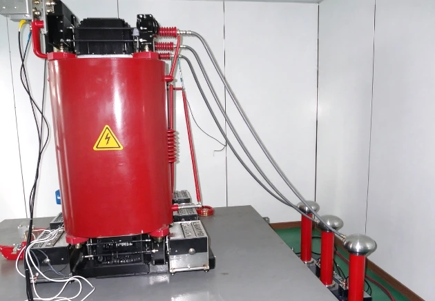
Testing Equipment: Partial Discharge Measuring System
Basic Procedure: Apply test voltage as per the standard and record the partial discharge activity with the help of a partial discharge measuring system. Write down the apparent charge in picocoulomb (pC) and compare with the acceptance limit.
OMEK Standards: Test results are based on customer technical agreements or project specifications.
Risks of Failure: Excessive partial discharge may lead to voids, cracks or other defects in insulation. Over time these flaws can cause insulation to become increasingly compromised and electrical failure.
Tank Leak or Tightness Test (Oil-Immersed Transformers)
To prevent insulating oil leakage during operation to verify the sealing integrity of the tank and identify oil leakage around the weld, gasket and connection.
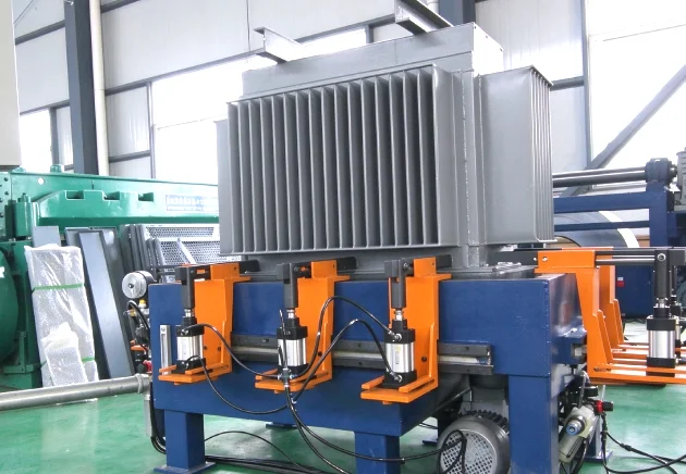
Testing Equipment: Pressure Gauge and Pressure Testing Equipment
Basic Procedure: Apply pressure to the sealed transformer tank, check for leakage throughout the test period on the tank, welds, and connections.
OMEK Standards: Apply a test pressure of 20 kPa for 12 hours. The test passes if no leakage is found during the test period.
Risks of Failure: Tank leakage may cause insulating oil loss, weaken insulation and cooling performance, and allow moisture to enter the transformer, increasing the risk of insulation deterioration and equipment failure.
Insulating Liquid Tests (Oil-Immersed Transformers)
These tests assess oil purity and insulating performance, and to detect excessive contaminants and moisture in the insulating oil.
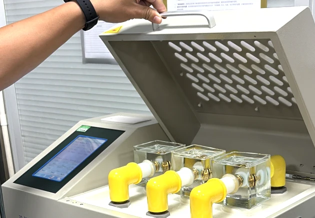
Testing Equipment: Insulating Oil Breakdown Voltage Tester, Oil Dielectric Dissipation Factor Tester, Oil Moisture Content Analyzer
Basic Procedure: Collect an oil sample using a clean sampling container. Test its breakdown voltage, dielectric dissipation factor, and moisture content using the appropriate instruments.
OMEK Standards: The test lasts for 30 minutes. While the national standard specifies 40 kV and the mandatory standard requires 45 kV, OMEK adopts a minimum breakdown voltage of 45 kV for all tests.
Risks of Failure: Low breakdown voltage may indicate moisture or contaminants in the oil, reducing its insulating strength. Excessive moisture or dielectric loss may accelerate insulation deterioration and increase the risk of electrical failure.
On-Load Tap-Changer Operation Test (If Equipped with an OLTC)
To verify that OLTC functions well and accurately in all tap positions, so that the voltage can be adjusted without any interruption to the power supply.
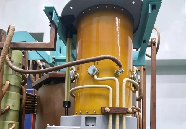
Testing Equipment: OLTC Control Unit and Position Indicator, OLTC Motor Drive Mechanism
Basic Procedure: Operate the OLTC through its tap positions. Check if each position shifts correctly, position indicator matches the actual tap position, and the operating mechanism works.
Risks of Failure: An OLTC failure may result in faulty electrical contact or wear of contact, or improper tap positioning, which all of these cause failures of the transformer.
Built-in Current Transformer Ratio and Polarity Check (If applicable)
To test the transformation ratio and the polarity of the built-in current transformers (CTs) and ensure the correct current measurement and the reliable operation of the transformer’s protection system.

Testing Equipment: CT Analyzer
Basic Procedure: Inject a known current into the primary circuit of the CT or use the appropriate CT test set. Check the secondary current to see if the CT ratio is correct; verify the secondary connections and polarity markings with the wiring diagram.
Risks of Failure: An incorrect CT ratio may cause faulty current readings, while incorrect polarity may lead to faulty protection signals or improper relay operation, failing to protect the transformer.
How to Read a Transformer Routine Test Report?
A routine test report helps buyers to check if the transformer is compliant with the agreed technical specifications and applicable standards.
✅️ Rated Parameters vs. Measured Values: Compare the measured test results with the required purchase specifications for rated voltage, capacity, vector group, etc.
✅️ Applicable Standards and Acceptance Limits: Ensure test results are within the appropriate IEC standards and agreed acceptance limits.
✅️ Test Results and Abnormal Records: Check pass/fail results, abnormal readings, and any corrective actions or retest records.
✅️ Buyer Acceptance Checklist: Verify the transformer serial number, required test coverage, test results, and authorized approval before delivery.
Conclusion
Transformer routine test is a very important test to confirm the quality of the manufactured product, find out the potential defect and prevent risk during operation before delivery. A review of test results, using applicable standards and agreed specification, will enable the buyer to ensure compliance and make an informed acceptance decision. When selecting a transformer manufacturer, trustworthy testing protocols can help assure long-lasting performance and reliability during operation.
Frequently Asked Questions
1. What is a routine test of transformer?
Transformer routine testing is conducted on every transformer during production to ensure that the transformer meets electrical performance, insulation level and specified requirements. Common tests include winding resistance, voltage ratio, load loss, no-load loss and dielectric tests. These tests vary according to the type of transformer and standards to which it must conform.
2.Do all transformers have mandatory routine tests?
Yes. Usually, each transformer is tested routinely prior to delivery to ensure that the transformer conforms with the applicable standards and technical requirements.
3.Which IEC standard applies to oil-immersed transformers?
The general requirements for power transformers, for example routine tests are given in IEC 60076-1. Insulation level and dielectric tests are specified in IEC 60076-3.
4.What happens if a transformer fails a routine test?
The manufacturer must find out the failure cause in routine tests, correct the defect, and repeat the tests. Approval to deliver the transformer shall not be given until the failure has been corrected and the necessary test results have been obtained that comply with applicable standards and agreed specifications.
5.Will the manufacturer provide a transformer routine test report?
Yes. Buyers can request a transformer routine test report from the manufacturer before delivery. The test results, measured values and necessary acceptance criteria should be provided in the report to ensure that the transformer complies with the agreed technical specifications and applicable standards.
6.How to test a transformer with a multimeter?
A multimeter can be used to do simple tests on a transformer, including checking for open circuit and continuity between the windings. It is unable, however, to confirm all the performance parameters or insulation strength of a transformer. Test equipment like voltage ratio, winding resistance and dielectric withstand are required. Disconnect the transformer from the power source and make sure the transformer is de-energized before testing.

Posted by Victoria leave words
Thanks for reading! Hope you enjoy this article. If you have any questions about this blog, please leave a comment below, or contact OMEK's online customer service. Looking forward to having in-depth communication with you!
Leave a Reply